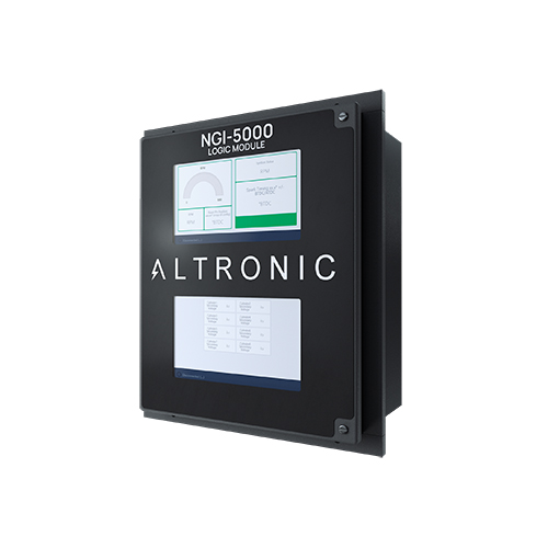
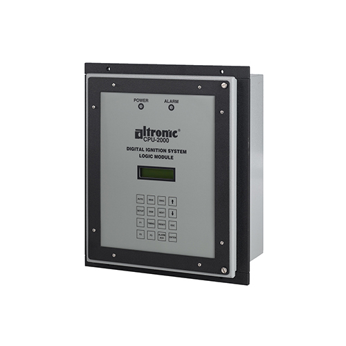
Supersedes existing CPU-2000 ignition system Logic Module (PN 291100-1)
- Drop-in replacement – enclosure, mounting, system wiring
- Dual, 7”, full HD (1080P), user-configurable, displays for system monitoring and control
- Incorporates the revolutionary Altronic Web Interface (AWI) for easy customization of displays
- Simple system configuration and integration with other control systems
- Future-proof, fully compatible with full NGI-5000 Ignition System
- Certified* for use in Class I, Division 2, Group C and D hazardous operating areas
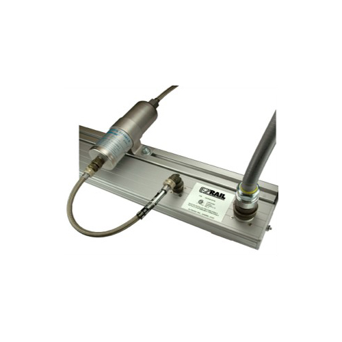
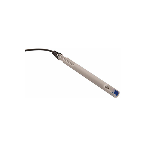
The NGI-5000 Logic Module developed for use with the full NGI-5000 Advanced Large Gas Engine Ignition System can also be easily deployed as a direct, drop-in replacement and upgrade for existing CPU-2000 ignition systems. Retention of this same module in a complete NGI-5000 installation allows for a cost-effective, two-step system upgrade process. Incorporating both a high-performance microcontroller and microprocessor, the NGI-5000 Logic Module seamless bridges the gap between the critical real-time control of the engine operation and the communication and interface with the outside world. Existing CPU-2000 installations can be seamlessly modernized with the NGI-5000 Logic Module eliminating the support burden of legacy communication standards and wearing EEPROMs. Dual 1080P displays are integrated into the logic module for unprecedented access to system data, configuration details, and user-configurable dashboards. Typically, one of the displays provides graphical indication of operating status, engine RPM, and ignition timing. The second display is generally configured to provide access to all other relevant system data and configuration details. In addition to supporting industry-standard Modbus RTU, the NGI-5000 logic module also incorporates an integral Ethernet switch, and provides a port for connection to external systems via Modbus TCP, the AWI tool, or other Ethernet-based protocols. Replacement of the existing CPU—2000 Logic Module with the NGI-5000 Logic Module is simple. The enclosure, mounting pattern, and wiring – including the use of the same pluggable terminal blocks and terminal layout – is retained in the NGI-5000 Module. All system configuration is accomplished through the AWI - no external terminal program is required. The NGI-5000 Logic Module is certified* for use in Class I, Division 2, Group C and D hazardous areas. INPUTS Magnetic Pickups (2) 1 – Flywheel holes or ring gear teeth 1 – Reset (1/engine revolution) 1 – Hall-effect pickup for compression stroke reference (4-cycle applications only) Timing Control
Inputs Analog:
4–20 mA control signal Communications:
Modbus RTU / TCP Manual:
Logic Module keypad, Misc. input terminal RS-485 serial communications — ModBus RTU communications 10/100 Ethernet – ModBus TCP, etc. DISPLAY Dual, 7”, full HD (1080P), sunlight-readable, 900 nits POWER REQUIREMENTS 24 Vdc, 5 Amps typical TEMPERATURE –40° F. to +158° F. –40° C. to +70° C. ORDERING INFORMATION NGI-5000 Logic Module
291500-1 (See CPU-2000 Application Instructions for additional details)
Product Info
Installation
Operating
Service / Support
