Installation Instructions
DESCRIPTION
The MTB-etc (enhance temperature control) is a new class of instrument that extends the temperature range for K thermocouples to 1100.0C (2012.0F) and the J thermocouples to 860.0C (1580.0F). All MTB-etc units are factory calibrated to +/- 1.0 degree C accuracy. Floating point displayed values are shown in tenths of a degree. See section 4.3 for more information how to setup the MTB-etc and the thermocouples to ensure the highest degree of accuracy. The MTB-etc is an RS-485, MODBUS RTU slave board capable of reading 33 channels. The first 30 channels can be any combination of digital inputs (N/O or N/C), thermocouples (J or K), pressure inputs, 4-20mA inputs, or read any sensor within the range of 0-5VDC. Channels 31 and 32 can only be used for digital inputs (N/O or N/C). There is also a pickup input. Additionally, there are 8 digital outputs which are capable of sinking 60V at 500mA. Each could drive a relay, horn, or other related device. There are also two 4-20mA outputs. All the outputs are directly controlled by RS-485 Modbus RTU commands. The Modbus Terminal Board is CSA-certified for CLASS I, DIVISION 2, GROUPS C and D areas, when mounted in a suitable enclosure.
The RS-485 communications is fixed at 38.4k baud, 8, N, 1. The Modbus node number for each board is selected through a mechanical switch on the board. Node numbers are from 1 to 9 allowing for up to 297 analog inputs to be daisy-chained onto one RS-485 port. This product may be used with PLC’s, HMI, or any application where inputs/ outputs are needed. It can be rail mounted for easy installation.
WARNING: DEVIATION FROM THESE INSTRUCTIONS MAY LEAD TO IMPROPER ENGINE/MACHINE OPERATION WHICH COULD CAUSE PERSONAL INJURY TO OPERATORS OR OTHER NEARBY PERSONNEL.
TERMINAL BOARD
SENSOR TYPES FOR CHANNELS 01-30
A removable, dual terminal strip is used to connect the system to the equipment-mounted, discrete sensors. These sensors can be used for either a normally-open switch, normally-closed switch, or analog inputs including K- or J-type thermocouples. These are listed as channels 01–30. They accept industry-standard transducer signals in the range of 0-5 VDC.
The Altronic part number for the MTB-etc is 691217-10.
TRANSDUCER COMPATIBILITY
The Modbus Terminal Board is designed to operate with industry-standard voltage – or current-amplified – output transducers in the range of 0 to 5Vdc or 0 to 25mA. Two series of transducers are available from Altronic: pressure transducers 691201-x, 691204-x, and temperature transducer 691202/203-300
PRESSURE TRANSDUCERS
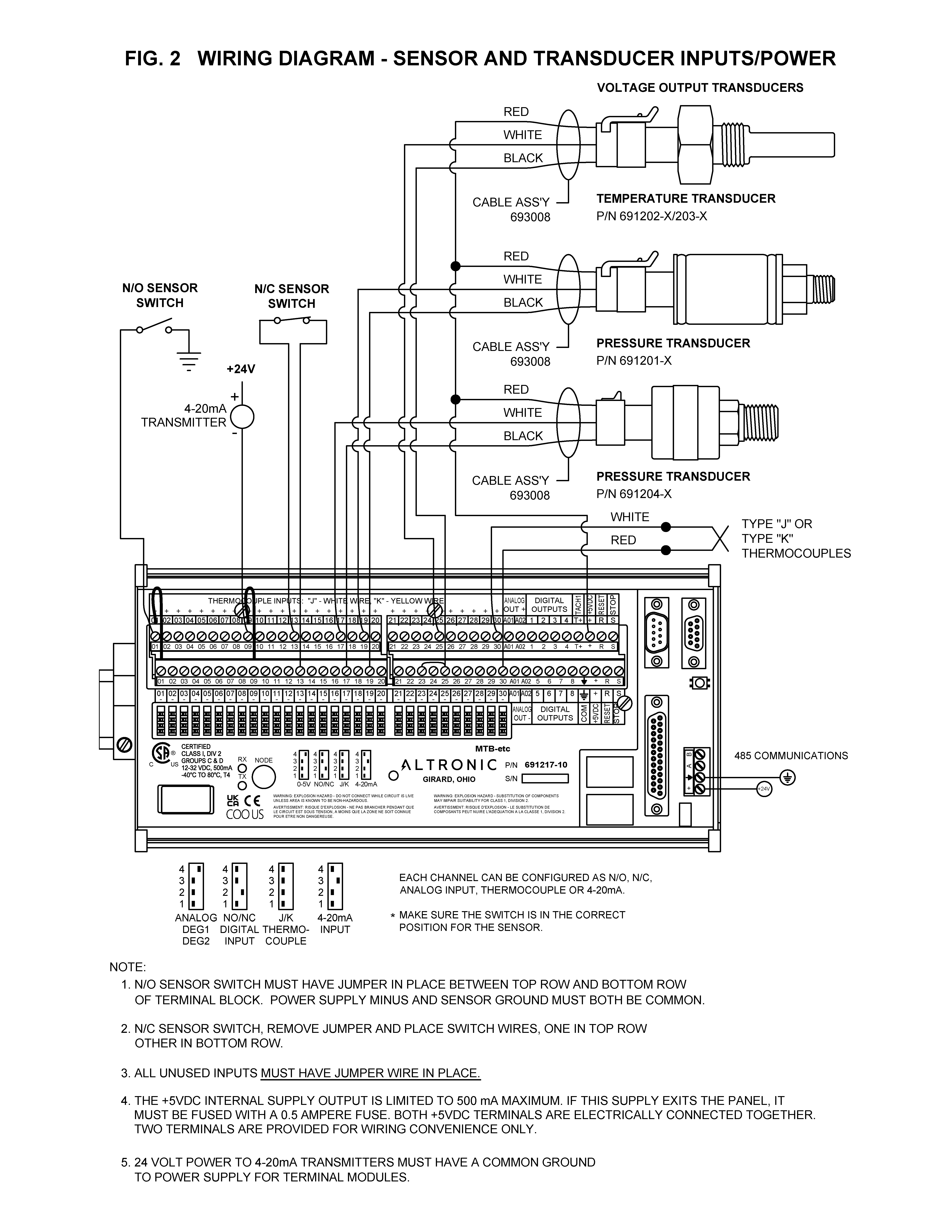
The pressure transducers, Altronic P/N 691201-x and P/N 691204-x, are packaged in a rugged, sealed case with a NPT pressure port, a corrosion resistant media cavity, and a Packard Electric Metri-Pack connector. The ranges available are 0-15, 0-25, 0-50, 0-100, 0-300, 0-500, 0-1000, 0-2000, and 0-5000 PSIG for the 691201-x series; and 0-15, 0-20, 0-30, 0-50, 0-100, 0-300, 0-500 PSIA for the 691204-x series. All have an overload rating of 1.5 times full scale without damage. The three wires from the transducer are: +5 volt excitation, +0.5 to 4.5 volt output, and minus return. These three wires connect directly to the back of the terminal board using cable assembly P/N 693008-x.
IMPORTANT: Pressure transducers will withstand overloads as high as 1.5 times rated pressure. If the overload rating is exceeded, failure may occur. Pressure fluctuations occur in most reciprocating systems; pick the transducer with a rating high enough to prevent overload by peak pressures of pulsations. It is recommended that a pressure snubber be used which will reduce the peak pressure applied to the transducer. The life of the transducer will be extended with the use of a snubber or pulsation dampener.
TEMPERATURE TRANSDUCER
The temperature transducers, Altronic P/N 691202-300, 691203-300 with a temperature measurement range of +5 to 300°F are packaged in a sealed, stainless steel housing with a 5/8“-18 UNF threaded body, and a Packard Electric Metri-Pack connector. The three wires from the transducer are: +5 volt excitation, temperature output voltage, and minus return. These wires connect directly to the terminal board using cable assembly P/N 693008-x.
IMPORTANT: Do not exceed the absolute maximum rating of the transducers, 350°F (176°C) for the 691202/203-300. Care should be taken to protect the wiring and connectors from contact with hot surfaces.
THERMOCOUPLE INPUTS
THERMOCOUPLE INPUTS The terminal board can accept industry standard type J or K thermocouples. Automatic cold junction compensation is built-in. The units can be configured to °F or °C. The MTB-etc can read type J thermocouples between -76.0°F and +1580.0°F (-60.0°C and +860.0°C) and type K thermocouples between -76.0°F and +2012.0°F (-60.0°C and +1100°C).
N/O and N/C INPUTS
The inputs can also accept standard normally-open and normally-closed contacts. Refer to figure 2 for proper wiring of these types of inputs.
4-20mA inputs
The terminal board can accept 4-20mA inputs by selecting the internally connected 200 ohm resistors, creating a termination voltage of .8 to 4.0 volts. The jumper wires between the + and – terminals for that channel must be connected for proper operation.
CHANNEL SWITCH
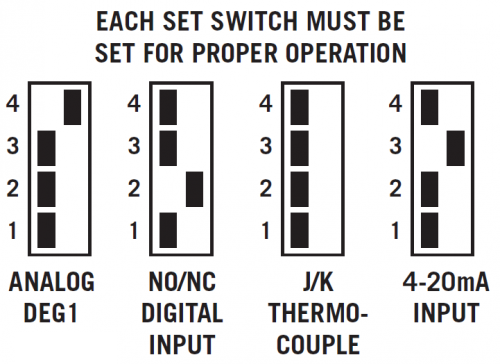
For each input, the corresponding CHANNEL SWITCH must be set according to the input type. Switches are turned ON by moving them toward the ANALOG OUT labeling.
PILOT DUTY OUTPUTS
Digital outputs 1 through 8 are pilot duty and turn on to common ground when closed. Outputs 1 through 8 are rated at 500mA, 60V.
MOUNTING
TERMINAL BOARD
Mount the Modbus Terminal Board either on the bottom or the side of the main panel. The terminal board can be rail-mounted onto commercially available 32 or 35 mm DIN mounting rails. The operating temperature range of the Terminal Module is −40°F to +176°F (−40°C to +80°C).
PRESSURE TRANSDUCER
Mount the pressure transducer in the panel or in a manifold or tube off of the engine. Do not expose the pressure transducer to temperatures above 221°F. (105°C). The second terminal module should be placed close to the first and the wire connecting them should be free of high-powered panel signals.
TEMPERATURE TRANSDUCER
Mount the temperature transducer in a thermowell on the engine or machine. The actual sensor is located at the bottom of the transducer body; to ensure accuracy, the tip of the probe should be surrounded by the measured media. The center of the pickup face must line up with the center of each drilled hole as the disc rotates.
WIRING
POWER
Connect the supply power wires to the 12-24Vdc input power terminals on the board, plus to terminal (+) and minus to terminal (−); power requirement is 12 to 24Vdc (10 watts max.). The DC− terminal must be connected to panel ground, which should be the same as engine ground. This is the return path for normally-open sensors and must be connected for proper operation. DO NOT ground this device directly to the ignition system common coil ground.
SENSOR WIRING DISCRETE INPUTS
The sensor leads connect to the removable terminal strips on the terminal board. Any discrete sensor point can be wired for normally-open or normally-closed operation.
■ Normally-open (N/O) sensor switches are wired with one wire to the bottom terminal strip of the respective sensor number and the other to engine ground which should be the same as power minus (−). A short jumper from the bottom terminal to the top terminal must be connected for normally-open sensors. (see wiring diagrams)
■ Normally-closed (N/C) sensor switches are wired with one wire to the bottom terminal strip and the other to the top terminal strip of the respective sensor number. Note that the short jumper wire must be removed. Use a wire size between 16 AWG (max.) and 24 AWG (min.) to connect the sensor switches to the terminal strip connector. Strip the insulation back 3/8”; twist the exposed wires tightly together. Insert the exposed wire completely into the terminal strip and securely tighten the clamping screw. Wires running to sensor switches must be in good condition or replaced with new wires. When running wires, take care not to damage the insulation and take precautions against later damage from vibration, abrasion, or liquids in conduits. An explosion-proof conduit is not required. However; wires should be protected from damage by running them in a protective conduit or in sheaths where appropriate. In addition, it is essential that the following practices be adhered to:
A. Never run sensor wires in the same conduit with ignition wiring or other high energy wiring such as the AC line power.
B. Keep secondary wires to spark plugs and other high voltage wiring at least eight inches (200mm) away from sensor and sensor wiring.
C. Sensor switches may be connected to any passive device using contacts such as standard switch gauges, pressure or level switches. DO NOT connect sensor leads to any voltage producing element.
D. If it becomes necessary to check sensor switch to panel wiring with an ohmmeter or other checker, first DISCONNECT the plug-in terminal strips from the Terminal Module. Applying voltage to the Modbus terminal board through the sensor leads may damage the device. The area should be tested as non-hazardous before such testing commences.
ANALOG SENSOR WIRING
For each analog monitored point, select a transducer—either an Altronic pressure or temperature transducer listed above or one that outputs a signal in the range of 0 to 5Vdc or 0 to 25mA. Mount as described above. Use cable assembly 693008-x or similar to wire transducer to the Modbus terminal board. An internal 5 volt sensor supply (500mA max.) is available to power the Altronic transducers; see wiring diagrams. If the 5 volt sensor supply exits the panel, it must be fused with a 0.5 ampere fuse. If 24Vdc powered sensors are used, the 24 volt supply to them must be fused appropriately. Take care not to damage the insulation when installing and take precautions against later damage from vibration, abrasion, or liquids in conduits.
THERMOCOUPLES AND THERMOCOUPLE EXTENSION WIRE
Grounded or ungrounded type J or K thermocouples may be used. Use thermocouple extension wire of the same type as the thermocouple probe to connect to the terminal module. Use stranded thermocouple wire having a moisture-resistant insulation such as PVC; for higher ambient temperatures, Teflon or B-fibre insulated thermocouple wire is recommended. To ensure that an accurate signal is transmitted to the device, avoid any added junctions, splices and contact with other metals. On unused channels, leave the small jumper wire supplied with the system in place. Take care not to damage the insulation when installing and take precautions against later damage from vibration, abrasion, or liquids in conduits. In addition, it is essential that the following practices be adhered to:
A. Never run sensor wires in the same conduit with ignition wiring or other high energy wiring such as AC line power.
B. Keep secondary wires to spark plugs and other high voltage wiring at least eight inches (200mm) away from sensor and sensor wiring.
C. The slope and intercept values for thermocouples has been factory calibrated for each channel of the MTB-etc board. Ensure these values are not over-written when using thermocouples. Altronic maintains the factory calibration values associated with each board and are available upon request.
D. The user can change one Modbus register to switch from J to K thermocouples and visa versa. Set register 40189 to ‘0’ to make all channels J thermocouples and set it to ‘1’ to make them all channels K thermocouples. Individual channels may be selected to either J or K type thermocouples.
RS-485 COMMUNICATIONS WIRING
There is one RS-485 communication port: Use a two-conductor shielded cable of fine gauge stranded wire and connect the wires to the terminals marked A and B.
SENSE ROTATION INPUT
The T+ terminal on the Modbus terminal board can be used as a speed input. The T+ input is only for use with magnetic pickups. This input monitors a magnetic pickup monitoring an engine-mounted gear.
HAZARDOUS AREA OPERATION
CSA CERTIFICATION
The Modbus Terminal Board is CSA certified for CLASS I, DIVISION 2, GROUPS C and D areas, when mounted in a suitable enclosure. In addition, the following requirements must be met (refer to NFPA standard No. 493):
■ The low voltage sensor switch wires within the panel enclosure must be kept at least two (2) inches away from other wiring. Run the sensor switch wires leaving the panel in a separate conduit from all other wiring and keep them separate.
■ Wiring to the sensors must have a grade of insulation capable of withstanding an AC voltage of 500 volts RMS.
■ Sensor wires must be run in separate conduits and junction boxes from high voltage wires such as ignition, fuel valve, and other high voltage wiring.
CONFIGURING THE MODBUS CHANNELS
COMMUNICATION CONFIGURATION
The configuration for setting up the communications are as follows:
BAUD RATE: 38.4K
DATA BITS: 8
PARITY: NO
STOP BITS: 1
These values are fixed and cannot be changed.
The node number can be changed by moving the mechanical switch to the desired number. Valid values are from 1 to 9. RS-485 units which are daisychained together must have unique node numbers. Zero is not a valid node number.
MODBUS TERMINAL BOARD CONFIGURATION
The Modbus Terminal Board must be configured prior to use. This typically requires the channels to be configured for the type of sensor to be used. Modbus registers 40067 – 40286 are responsible for configuring all the channel configurations and are stored in FLASH/EE memory and have a maximum of 100k write cycle endurance. These Modbus registers will retain their value even after a power down. Registers greater than 40769 are stored in RAM locations and may be written as many times as needed and are cleared (00h) after a power up condition.
CONFIGURING STANDARD ANALOG CHANNELS
In order to configure a channel for a particular type of input, 5 Modbus registers must first be configured according to section 9. Configuring the channels entails entering the numbers according to the chart. For example, to configure channel 12 for a 0-50 PSI transducer from a standard Altronic transducer, the following registers must be programmed:
40113 – 213
40114 – 5464
40115 – (-125)
40116 – 625
40268 – 1
This allows channel 12, registers 30023-30024, to display a swapped floating point for that particular channel.
CHANNEL 32 – SPECIAL FUNCTION
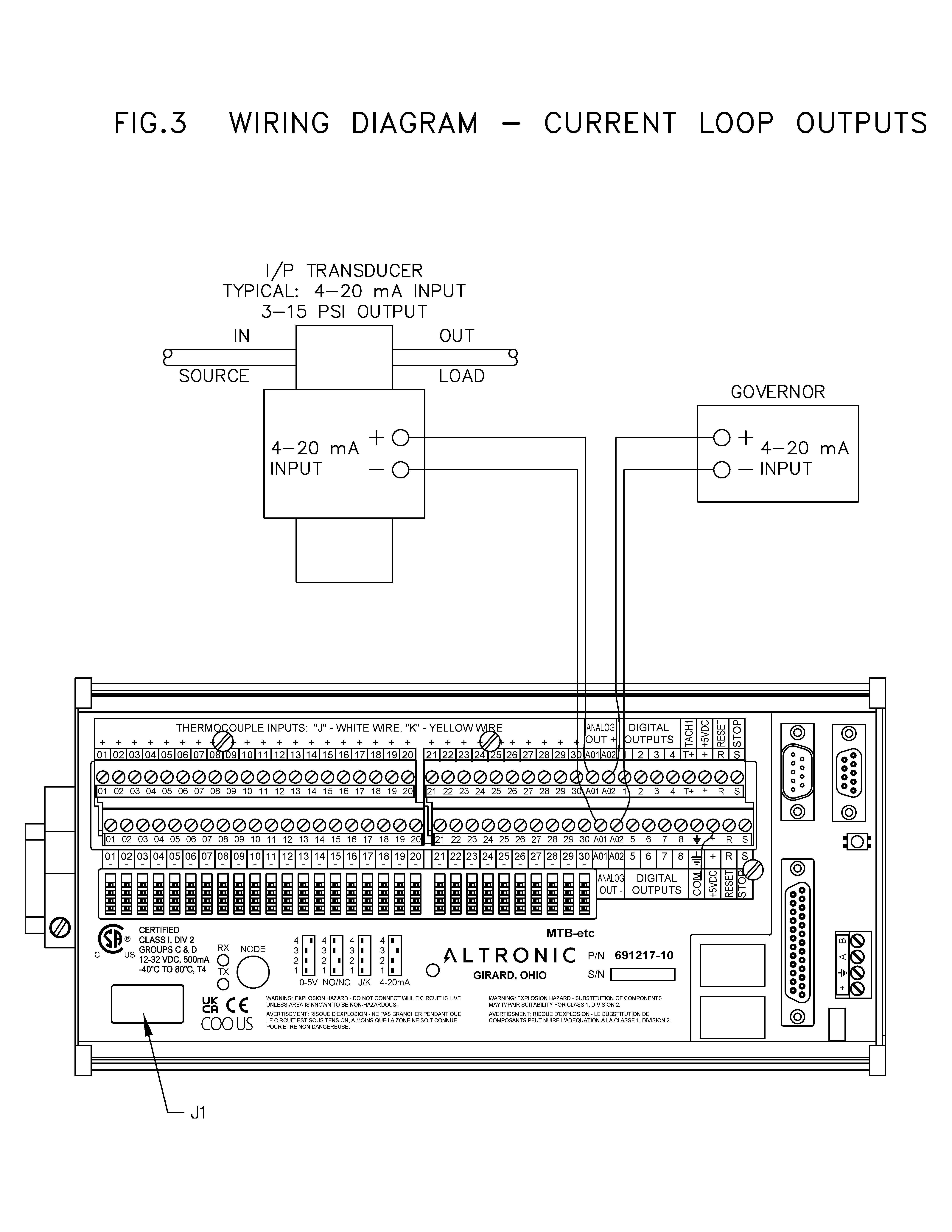
When the input has been violated, this will cause the digital outputs to all turn off and the 4-20mA outputs to immediately go to a pre-configured state as defined by Modbus registers 40067 and 40068.
CONFIGURING NON-STANDARD ANALOG CHANNELS
The sensor must be a linear signal in order for the displayed value to be read correctly. Many HMI/PLCs can ‘linearize’ the input signal.
To properly understand how to configure the channel, it is first necessary to know how the sensor relationship between voltage and displayed value (pressure, temperature, other) works.
Given the example in section 6.3, a standard 0 – 50 PSI sensor will be examined. For the Altronic style sensor, .5V will display 0.0 PSI and 4.5V will display 50.0 PSI. Refer to Voltage vs Pressure chart.
NOTE: Modbus write commands will NOT be accepted unless the 40772 register contains 5300h. This may be used to protect against accidental writes to critical memory locations
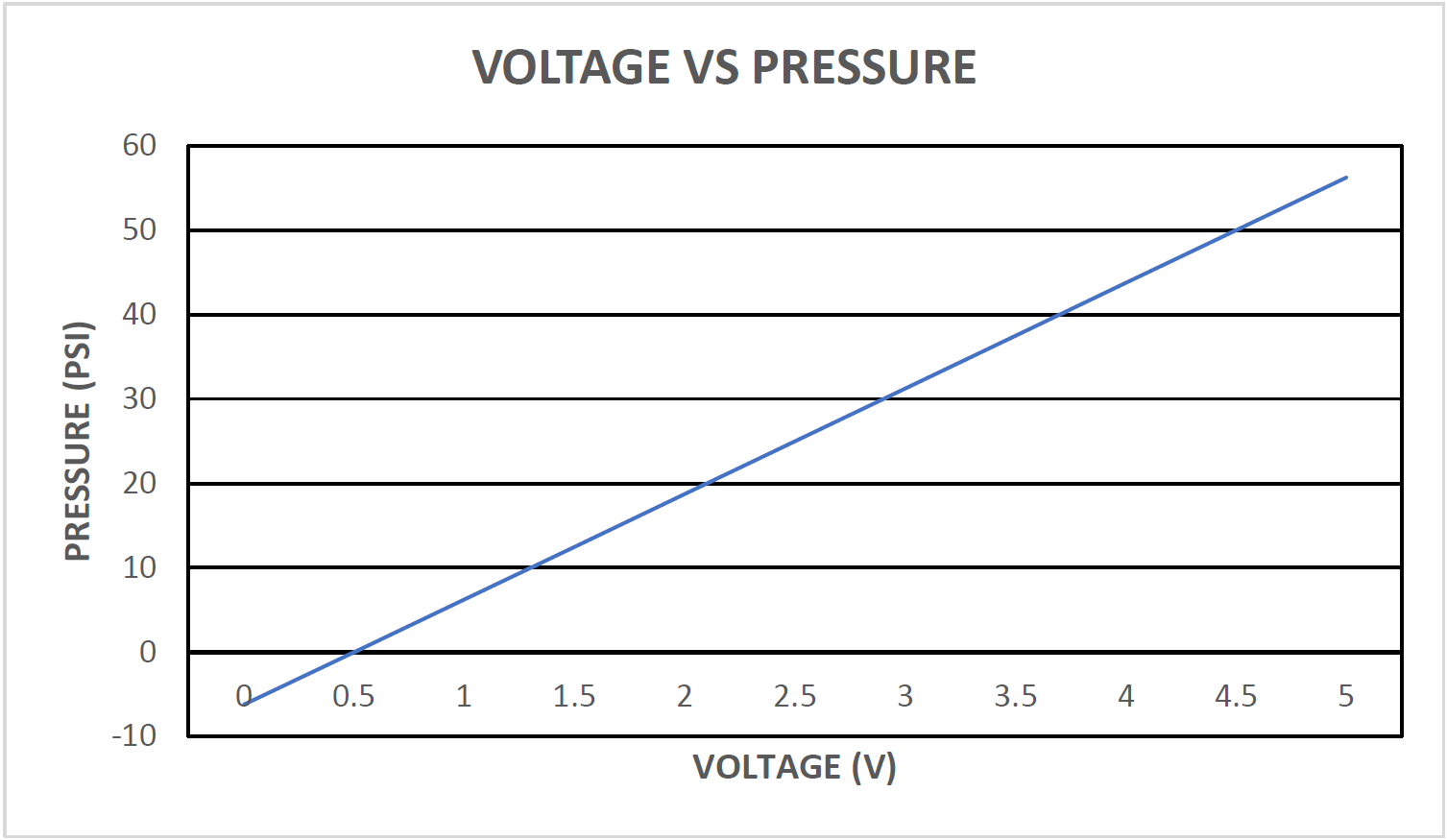
As those 2 points are created in the chart, a line may be drawn between them showing the relationship between voltage and pressure.
At 0V, the displayed value (according to the chart) would be -6.25 and 5V would be 56.25 PSI. It is rounded to -6.2 and 56.2 for one decimal point placement. Register 40115 is set for -125 and 40116 is set for 625. This corresponds to -12.5 and 62.5 with register 40268 set for 1 for the decimal point.
40113 corresponds to the offset of the 0V point. Using the -6.25 value for the low, the difference between this value and -12.5 is (-6.25-(-12.5) = 6.25
The overall value of the sensor is 62.5 – (-12.5) = 75.0
To calculate the value, use the following expression:
(6.25/75.0) * 65535 = 5461. The slightly greater value for Modbus register 40114 of 5464 was due to some slight errors due to internal protection circuits. With this offset value, 0V in would yield a displayed value of -6.2 for this example. A larger number could give you, lets say 0 PSI for 0V and a smaller number (0) would yield -12.5 for 0V.
40113 is responsible for showing the slope of the line. This can be calculated as follows: 40113 = 256 * ((change in Y) / (total range of Y)) / ((change in voltage) / (total range of voltage)) NOTE: total range of voltage will always be 5V.
40113 = 256 * ((50 – 0) / (62.5 – (-12.5))) / ((4.5 – .5) / 5)
40113 = 256 * ((50 / (75)) / (4 / 5)
40113 = 256 * (.6666) / (0.8)
40113 = 213.12
This value should be rounded to 213.
This number should never be greater than 512.
TROUBLESHOOTING
7.1 The power LED on the board is not illuminated
■ Check the power supply voltage at the 12-24Vdc input terminals; should be between 12 and 24Vdc.
7.2 Neither the RX nor the TX lights are flashing
■ Modbus Terminal Board is not receiving any MODBUS commands. ■ Check wiring and communications coming from the Modbus master.
7.3 RX light is flashing, but the Modbus Terminal Board is not responding
■ Verify the baud rate at 38.4k, 8 data bits, no parity and one stop bit.
■ Verify the node number is correct and corresponds to the node selection on the Modbus Terminal Board.
■ Verify that Modbus address registers are correct.
■ Replace the Modbus Terminal Board.
MODBUS ADDRESS LIST
| Registers | Description | Data Type | Note |
|---|---|---|---|
| 30001 | CHANNEL 1 | SWAPPED FP | |
| 30002 | |||
| 30003 | CHANNEL 2 | SWAPPED FP | |
| 30004 | |||
| 30005 | CHANNEL 3 | SWAPPED FP | |
| 30006 | |||
| 30007 | CHANNEL 4 | SWAPPED FP | |
| 30008 | |||
| 30009 | CHANNEL 5 | SWAPPED FP | |
| 30010 | |||
| 30011 | CHANNEL 6 | SWAPPED FP | |
| 30012 | |||
| 30013 | CHANNEL 7 | SWAPPED FP | |
| 30014 | |||
| 30015 | CHANNEL 8 | SWAPPED FP | |
| 30016 | |||
| 30017 | CHANNEL 9 | SWAPPED FP | |
| 30018 | |||
| 30019 | CHANNEL 10 | SWAPPED FP | |
| 30020 | |||
| 30021 | CHANNEL 11 | SWAPPED FP | |
| 30022 | |||
| 30023 | CHANNEL 12 | SWAPPED FP | |
| 30024 | |||
| 30025 | CHANNEL 13 | SWAPPED FP | |
| 30026 | |||
| 30027 | CHANNEL 14 | SWAPPED FP | |
| 30028 | |||
| 30029 | CHANNEL 15 | SWAPPED FP | |
| 30030 | |||
| 30031 | CHANNEL 16 | SWAPPED FP | |
| 30032 | |||
| 30033 | CHANNEL 17 | SWAPPED FP | |
| 30034 | |||
| 30035 | CHANNEL 18 | SWAPPED FP | |
| 30036 | |||
| 30037 | CHANNEL 19 | SWAPPED FP | |
| 30038 | |||
| 30039 | CHANNEL 20 | SWAPPED FP | |
| 30040 | |||
| 30041 | CHANNEL 21 | SWAPPED FP | |
| 30042 | |||
| 30043 | CHANNEL 22 | SWAPPED FP | |
| 30044 | |||
| 30045 | CHANNEL 23 | SWAPPED FP | |
| 30046 | |||
| 30047 | CHANNEL 24 | SWAPPED FP | |
| 30048 | |||
| 30049 | CHANNEL 25 | SWAPPED FP | |
| 30050 | |||
| 30051 | CHANNEL 26 | SWAPPED FP | |
| 30052 | |||
| 30053 | CHANNEL 27 | SWAPPED FP | |
| 30054 | |||
| 30055 | CHANNEL 28 | SWAPPED FP | |
| 30056 | |||
| 30057 | CHANNEL 29 | SWAPPED FP | |
| 30058 | |||
| 30059 | CHANNEL 30 | SWAPPED FP | |
| 30060 | |||
| 30061 | SPEED | SWAPPED FP | |
| 30062 | |||
| 30063 | AMBIENT TEMPERATURE | UNSIGNED INT | Displayed in ‘tenths’ of Kelvins. 2954 = 295.4K = 22.4C |
| 30064 | CHANNEL 31 | 0, or 1 (digital input only) | |
| 30065 | CHANNEL 32 | 0, or 1 (digital input only) | |
| 30066 | firmware month | ASCII | |
| 30067 | firmware date | ASCII | |
| 30068 | firmware year | ASCII | |
| 40067 | Special analog out #1, occurs when ch32 is tripped. See section 6.4. | ||
| 40068 | Special analog out #2, occurs when ch32 is tripped. See section 6.4. | ||
| 40069 | SLOPE, X | SIGNED INT | 1 |
| 40070 | OFFSET, B | SIGNED INT | 1 |
| 40071 | MINIMUM DISPLAYED NUMBER | SIGNED INT | 1 |
| 40072 | MAXIMUM DISPLAYED NUMBER | SIGNED INT | 1 |
| 40073 | SLOPE, X | SIGNED INT | 2 |
| 40074 | OFFSET, B | SIGNED INT | 2 |
| 40075 | MINIMUM DISPLAYED NUMBER | SIGNED INT | 2 |
| 40076 | MAXIMUM DISPLAYED NUMBER | SIGNED INT | 2 |
| 40077 | SLOPE, X | SIGNED INT | 3 |
| 40078 | OFFSET, B | SIGNED INT | 3 |
| 40079 | MINIMUM DISPLAYED NUMBER | SIGNED INT | 3 |
| 40080 | MAXIMUM DISPLAYED NUMBER | SIGNED INT | 3 |
| 40081 | SLOPE, X | SIGNED INT | 4 |
| 40082 | OFFSET, B | SIGNED INT | 4 |
| 40083 | MINIMUM DISPLAYED NUMBER | SIGNED INT | 4 |
| 40084 | MAXIMUM DISPLAYED NUMBER | SIGNED INT | 4 |
| 40085 | SLOPE, X | SIGNED INT | 5 |
| 40086 | OFFSET, B | SIGNED INT | 5 |
| 40087 | MINIMUM DISPLAYED NUMBER | SIGNED INT | 5 |
| 40088 | MAXIMUM DISPLAYED NUMBER | SIGNED INT | 5 |
| 40089 | SLOPE, X | SIGNED INT | 6 |
| 40090 | OFFSET, B | SIGNED INT | 6 |
| 40091 | MINIMUM DISPLAYED NUMBER | SIGNED INT | 6 |
| 40092 | MAXIMUM DISPLAYED NUMBER | SIGNED INT | 6 |
| 40093 | SLOPE, X | SIGNED INT | 7 |
| 40094 | OFFSET, B | SIGNED INT | 7 |
| 40095 | MINIMUM DISPLAYED NUMBER | SIGNED INT | 7 |
| 40096 | MAXIMUM DISPLAYED NUMBER | SIGNED INT | 7 |
| 40097 | SLOPE, X | SIGNED INT | 8 |
| 40098 | OFFSET, B | SIGNED INT | 8 |
| 40099 | MINIMUM DISPLAYED NUMBER | SIGNED INT | 8 |
| 40100 | MAXIMUM DISPLAYED NUMBER | SIGNED INT | 8 |
| 40101 | SLOPE, X | SIGNED INT | 9 |
| 40102 | OFFSET, B | SIGNED INT | 9 |
| 40103 | MINIMUM DISPLAYED NUMBER | SIGNED INT | 9 |
| 40104 | MAXIMUM DISPLAYED NUMBER | SIGNED INT | 9 |
| 40105 | SLOPE, X | SIGNED INT | 10 |
| 40106 | OFFSET, B | SIGNED INT | 10 |
| 40107 | MINIMUM DISPLAYED NUMBER | SIGNED INT | 10 |
| 40108 | MAXIMUM DISPLAYED NUMBER | SIGNED INT | 10 |
| 40109 | SLOPE, X | SIGNED INT | 11 |
| 40110 | OFFSET, B | SIGNED INT | 11 |
| 40111 | MINIMUM DISPLAYED NUMBER | SIGNED INT | 11 |
| 40112 | MAXIMUM DISPLAYED NUMBER | SIGNED INT | 11 |
| 40113 | SLOPE, X | SIGNED INT | 12 |
| 40114 | OFFSET, B | SIGNED INT | 12 |
| 40115 | MINIMUM DISPLAYED NUMBER | SIGNED INT | 12 |
| 40116 | MAXIMUM DISPLAYED NUMBER | SIGNED INT | 12 |
| 40117 | SLOPE, X | SIGNED INT | 13 |
| 40118 | OFFSET, B | SIGNED INT | 13 |
| 40119 | MINIMUM DISPLAYED NUMBER | SIGNED INT | 13 |
| 40120 | MAXIMUM DISPLAYED NUMBER | SIGNED INT | 13 |
| 40121 | SLOPE, X | SIGNED INT | 14 |
| 40122 | OFFSET, B | SIGNED INT | 14 |
| 40123 | MINIMUM DISPLAYED NUMBER | SIGNED INT | 14 |
| 40124 | MAXIMUM DISPLAYED NUMBER | SIGNED INT | 14 |
| 40125 | SLOPE, X | SIGNED INT | 15 |
| 40126 | OFFSET, B | SIGNED INT | 15 |
| 40127 | MINIMUM DISPLAYED NUMBER | SIGNED INT | 15 |
| 40128 | MAXIMUM DISPLAYED NUMBER | SIGNED INT | 15 |
| 40129 | SLOPE, X | SIGNED INT | 16 |
| 40130 | OFFSET, B | SIGNED INT | 16 |
| 40131 | MINIMUM DISPLAYED NUMBER | SIGNED INT | 16 |
| 40132 | MAXIMUM DISPLAYED NUMBER | SIGNED INT | 16 |
| 40133 | SLOPE, X | SIGNED INT | 17 |
| 40134 | OFFSET, B | SIGNED INT | 17 |
| 40135 | MINIMUM DISPLAYED NUMBER | SIGNED INT | 17 |
| 40136 | MAXIMUM DISPLAYED NUMBER | SIGNED INT | 17 |
| 40137 | SLOPE, X | SIGNED INT | 18 |
| 40138 | OFFSET, B | SIGNED INT | 18 |
| 40139 | MINIMUM DISPLAYED NUMBER | SIGNED INT | 18 |
| 40140 | MAXIMUM DISPLAYED NUMBER | SIGNED INT | 18 |
| 40141 | SLOPE, X | SIGNED INT | 19 |
| 40142 | OFFSET, B | SIGNED INT | 19 |
| 40143 | MINIMUM DISPLAYED NUMBER | SIGNED INT | 19 |
| 40144 | MAXIMUM DISPLAYED NUMBER | SIGNED INT | 19 |
| 40145 | SLOPE, X | SIGNED INT | 20 |
| 40146 | OFFSET, B | SIGNED INT | 20 |
| 40147 | MINIMUM DISPLAYED NUMBER | SIGNED INT | 20 |
| 40148 | MAXIMUM DISPLAYED NUMBER | SIGNED INT | 20 |
| 40149 | SLOPE, X | SIGNED INT | 21 |
| 40150 | OFFSET, B | SIGNED INT | 21 |
| 40151 | MINIMUM DISPLAYED NUMBER | SIGNED INT | 21 |
| 40152 | MAXIMUM DISPLAYED NUMBER | SIGNED INT | 21 |
| 40153 | SLOPE, X | SIGNED INT | 22 |
| 40154 | OFFSET, B | SIGNED INT | 22 |
| 40155 | MINIMUM DISPLAYED NUMBER | SIGNED INT | 22 |
| 40156 | MAXIMUM DISPLAYED NUMBER | SIGNED INT | 22 |
| 40157 | SLOPE, X | SIGNED INT | 23 |
| 40158 | OFFSET, B | SIGNED INT | 23 |
| 40159 | MINIMUM DISPLAYED NUMBER | SIGNED INT | 23 |
| 40160 | MAXIMUM DISPLAYED NUMBER | SIGNED INT | 23 |
| 40161 | SLOPE, X | SIGNED INT | 24 |
| 40162 | OFFSET, B | SIGNED INT | 24 |
| 40163 | MINIMUM DISPLAYED NUMBER | SIGNED INT | 24 |
| 40164 | MAXIMUM DISPLAYED NUMBER | SIGNED INT | 24 |
| 40165 | SLOPE, X | SIGNED INT | 25 |
| 40166 | OFFSET, B | SIGNED INT | 25 |
| 40167 | MINIMUM DISPLAYED NUMBER | SIGNED INT | 25 |
| 40168 | MAXIMUM DISPLAYED NUMBER | SIGNED INT | 25 |
| 40169 | SLOPE, X | SIGNED INT | 26 |
| 40170 | OFFSET, B | SIGNED INT | 26 |
| 40171 | MINIMUM DISPLAYED NUMBER | SIGNED INT | 26 |
| 40172 | MAXIMUM DISPLAYED NUMBER | SIGNED INT | 26 |
| 40173 | SLOPE, X | SIGNED INT | 27 |
| 40174 | OFFSET, B | SIGNED INT | 27 |
| 40175 | MINIMUM DISPLAYED NUMBER | SIGNED INT | 27 |
| 40176 | MAXIMUM DISPLAYED NUMBER | SIGNED INT | 27 |
| 40177 | SLOPE, X | SIGNED INT | 28 |
| 40178 | OFFSET, B | SIGNED INT | 28 |
| 40179 | MINIMUM DISPLAYED NUMBER | SIGNED INT | 28 |
| 40180 | MAXIMUM DISPLAYED NUMBER | SIGNED INT | 28 |
| 40181 | SLOPE, X | SIGNED INT | 29 |
| 40182 | OFFSET, B | SIGNED INT | 29 |
| 40183 | MINIMUM DISPLAYED NUMBER | SIGNED INT | 29 |
| 40184 | MAXIMUM DISPLAYED NUMBER | SIGNED INT | 29 |
| 40185 | SLOPE, X | SIGNED INT | 30 |
| 40186 | OFFSET, B | SIGNED INT | 30 |
| 40187 | MINIMUM DISPLAYED NUMBER | SIGNED INT | 30 |
| 40188 | MAXIMUM DISPLAYED NUMBER | SIGNED INT | 30 |
| 40189 | THERMOCOUPLE SELECTION | UNSIGNED INT | 0 = ALL CHANNELS J TC, 1 = ALL CHANNELS K TC |
| 40209 | PULSES PER REVOLUTION / 2 | UNSIGNED INT | |
| 40257 | DECIMAL POINT / SENSOR CONFIG | UNSIGNED INT | 1 |
| 40258 | DECIMAL POINT / SENSOR CONFIG | UNSIGNED INT | 2 |
| 40259 | DECIMAL POINT / SENSOR CONFIG | UNSIGNED INT | 3 |
| 40260 | DECIMAL POINT / SENSOR CONFIG | UNSIGNED INT | 4 |
| 40261 | DECIMAL POINT / SENSOR CONFIG | UNSIGNED INT | 5 |
| 40262 | DECIMAL POINT / SENSOR CONFIG | UNSIGNED INT | 6 |
| 40263 | DECIMAL POINT / SENSOR CONFIG | UNSIGNED INT | 7 |
| 40264 | DECIMAL POINT / SENSOR CONFIG | UNSIGNED INT | 8 |
| 40265 | DECIMAL POINT / SENSOR CONFIG | UNSIGNED INT | 9 |
| 40266 | DECIMAL POINT / SENSOR CONFIG | UNSIGNED INT | 10 |
| 40267 | DECIMAL POINT / SENSOR CONFIG | UNSIGNED INT | 11 |
| 40268 | DECIMAL POINT / SENSOR CONFIG | UNSIGNED INT | 12 |
| 40269 | DECIMAL POINT / SENSOR CONFIG | UNSIGNED INT | 13 |
| 40270 | DECIMAL POINT / SENSOR CONFIG | UNSIGNED INT | 14 |
| 40271 | DECIMAL POINT / SENSOR CONFIG | UNSIGNED INT | 15 |
| 40272 | DECIMAL POINT / SENSOR CONFIG | UNSIGNED INT | 16 |
| 40273 | DECIMAL POINT / SENSOR CONFIG | UNSIGNED INT | 17 |
| 40274 | DECIMAL POINT / SENSOR CONFIG | UNSIGNED INT | 18 |
| 40275 | DECIMAL POINT / SENSOR CONFIG | UNSIGNED INT | 19 |
| 40276 | DECIMAL POINT / SENSOR CONFIG | UNSIGNED INT | 20 |
| 40277 | DECIMAL POINT / SENSOR CONFIG | UNSIGNED INT | 21 |
| 40278 | DECIMAL POINT / SENSOR CONFIG | UNSIGNED INT | 22 |
| 40279 | DECIMAL POINT / SENSOR CONFIG | UNSIGNED INT | 23 |
| 40280 | DECIMAL POINT / SENSOR CONFIG | UNSIGNED INT | 24 |
| 40281 | DECIMAL POINT / SENSOR CONFIG | UNSIGNED INT | 25 |
| 40282 | DECIMAL POINT / SENSOR CONFIG | UNSIGNED INT | 26 |
| 40283 | DECIMAL POINT / SENSOR CONFIG | UNSIGNED INT | 27 |
| 40284 | DECIMAL POINT / SENSOR CONFIG | UNSIGNED INT | 28 |
| 40285 | DECIMAL POINT / SENSOR CONFIG | UNSIGNED INT | 29 |
| 40286 | DECIMAL POINT / SENSOR CONFIG | UNSIGNED INT | 30 |
| 40769 | DIGITAL OUTPUTS UNSIGNED | INT, LSB | |
| 40770 | ANALOG OUTPUT #1 UNSIGNED | INT 0 | 4095 |
| 40771 | ANALOG OUTPUT #2 UNSIGNED | INT 0 | 4095 |
| 40772 | MODBUS WRITE PROTECT | UNSIGNED IT | 5300H = WRITE ENABLE |
NOTE: Modbus write commands will NOT be accepted unless the 40772 register contains 5300h. This may be used to protect against accidental writes to critical memory locations.
TRANSDUCER TABLE
When displaying/modifying, it is important to the set the Modbus registers for the proper data type. For example, if the displayed value is -125 for a signed integer, it will display as 65410 as an unsigned integer.
| TRANSDUCER | SLOPE, X | OFFSET, B | MIN VALUE | MAX VALUE | D.P. CONFIG | COMMENTS |
|---|---|---|---|---|---|---|
| 0-50 | 213 | 5464 | -125 | 625 | 1 | |
| 0-100 | 213 | 5464 | -250 | 1250 | 1 | |
| 0-300 | 213 | 5464 | -750 | 375 | 1 | |
| 0-500 | 213 | 5464 | -1250 | 6250 | 0 | |
| 0-1000 | 213 | 5464 | -250 | 1250 | 0 | |
| 0-2000 | 213 | 5464 | -500 | 2500 | 0 | |
| 0-5000 | 213 | 5464 | -1250 | 6250 | 0 | |
| VOLTMETER | 255 | 0 | 0 | 500 | 2 | |
| 0-100.0%, 4-20mA | 267 | 76 | -250 | 1250 | 1 | |
| DEG1 | 432 | 0 | 0 | 300 | 0 | |
| J-TC, Celsius | ** | ** | -600 | 8600 | 513 | |
| J-TC, Fahrenheit | ** | ** | -760 | 15800 | 769 | |
| K-TC, Celsius | ** | ** | -600 | 11000 | 513 | |
| K-TC, Fahrenheit | ** | ** | -760 | 20120 | 769 | |
| DIG INPUT N/O | 852 | 5464 | -125 | 625 | 1025 | 0 = OK, 1 = FAULT |
| DIG INPUT N/C | 852 | 5464 | -125 | 625 | 1281 | 0 = OK, 1 = FAULT |
** Indicates factory calibration value should not be changed.
DRAWINGS SECTION
FIGURE 1 — MODBUS TERMINAL BOARD
FIGURE 2 — WIRING DIAGRAM — SENSOR AND TRANSDUCER INPUTS/POWER
FIGURE 3 — WIRING DIAGRAM — CURRENT LOOP OUTPUTS
FIGURE 4 — WIRING DIAGRAM — DIGITAL OUTPUT SWITCHES